How to Prevent and Fix Crack Defects in Powder Coating: A Complete Guide to Curing, Film Thickness & Process Control
When you spray powder coating onto a workpiece, the last thing you want to see is a surface covered in fine lines and fissures. Yet this happens to many coating operations—and when it does, production halts, customer complaints pile up, and costs spike. The problem isn't random. Cracks in powder coating follow a predictable pattern of root causes, and we can stop them before they start.
From our experience running powder coating production lines across cabinet manufacturing, aluminum extrusions, and outdoor furniture production, we've learned that crack defects are almost never a single-factor failure. They're the result of a chain reaction: improper cure temperature curves triggering thermal stress, film thickness applied too thick without accounting for workpiece geometry, inadequate pre-treatment leaving residual contamination, or a powder formulation chosen without considering substrate flexibility. When one link breaks, the whole chain fails.
Crack powder coating occurs when the cured coating develops fine lines or fissures on the surface, typically caused by excessive film thickness, overly rapid curing temperatures, or insufficient flexibility in the powder formulation. To prevent it, control cure temperature gradients to avoid thermal stress, maintain optimal film thickness within 60–120 microns, select flexible resin systems suited to your workpiece material, ensure thorough pre-treatment without residual contamination, and verify that cooling follows proper temperature profiles to minimize surface shrinkage stress.
The difference between a coating line that runs smoothly for years and one that constantly battles quality issues often comes down to understanding how these four factors—curing temperature curves, film thickness, surface preparation, and powder chemistry—interact. In this guide, we'll walk through each factor not as a textbook exercise, but as a practical framework that we apply when commissioning lines and troubleshooting field problems.
What Is Powder Coating Crack and Why Does It Matter?
Powder coating crack isn't a minor cosmetic issue. It's a structural failure that signals the coating has lost adhesion or internal integrity. When left unaddressed, cracks become entry points for moisture and corrosive agents, leading to substrate corrosion and coating failure within months—especially in outdoor or salt-spray environments.
Definition and Visual Characteristics
A crack in powder coating appears as a visible line, often radiating outward from stress points like corners, edges, or areas where geometry changes sharply. The crack may be hairline-thin or wide enough to expose the bare substrate underneath. In some cases, you'll see a "crazing" pattern—a web of interconnected fine lines that look almost like dried mud. The cracks typically emerge after curing, not during application, which means the coating looked acceptable coming out of the spray booth but failed during or after the cure cycle.
Cracks differ from other surface flaws in one key way: they indicate internal stress and material weakness, not just surface contamination or application technique. A pinhole or orange peel can sometimes be tolerated; a crack cannot.
How Cracks Differ from Other Powder Coating Defects
Understanding this distinction matters because your corrective action depends on diagnosis. A crater or shrimp-eye suggests pre-treatment or air quality problems. An orange peel suggests viscosity or flow issues. But a crack suggests thermomechanical failure—the coating is literally tearing itself apart because internal stresses exceed the material's ability to flex or relieve them.
| Defect Type | Root Cause | Visual Appearance | Structural Risk |
|---|---|---|---|
| Crack | Thermal stress, excessive thickness, low cure temp, poor formulation | Fine lines, radiating pattern, possible substrate exposure | High—adhesion compromised, corrosion pathway opened |
| Orange Peel | High viscosity, rapid cure, temperature spike, thick application | Bumpy texture, uniform overall surface | Medium—functional but compromises appearance and UV durability |
| Pinhole | Surface moisture, trapped gases, pre-treatment residue, compressed air quality | Small holes scattered across surface | Medium-High—moisture pathway, especially outdoors |
| Crazing | Rapid moisture loss, incompatible substrate or primer, low-flexibility resin | Fine web pattern, often clustered | High—indicates adhesion failure risk |
Root Causes of Powder Coating Cracks: The Four-Stage Failure Point Analysis
From our experience with over 200 customers in cabinet, furniture, and aluminum extrusion sectors, cracks almost always trace back to one of these four stages in the process. Understanding where your failure occurs is the fastest path to prevention.
Stage 1: Pre-Treatment & Surface Preparation
If the substrate surface isn't properly cleaned and treated, residual oils, salts, or moisture create a weak bond between coating and base metal. Even if the coating itself is perfectly formulated, it will crack and lift at the adhesion boundary. We typically see this when phosphate film thickness is too heavy, or when residual contamination remains after rinsing.
Stage 2: Spray Application & Film Build
Applying powder too thick in a single pass—especially on complex geometry—leaves uneven shrinkage during cure. Thick areas on flat surfaces and thin areas in corners create internal stress gradients. When the thick sections try to cure and contract, they pull against the thin sections, triggering cracking.
Stage 3: Cure Temperature Curve
This is where we see the most preventable failures. Raising temperature too fast creates a steep thermal gradient: the outer surface hardens rapidly while the interior is still soft, trapping stress. The material can't relieve this stress through flexing or molecular relaxation, so it cracks. Most problematic is undershooting the cure temperature or cutting hold time short—the coating never fully cross-links, so it lacks the molecular strength to resist shrinkage stress.
Stage 4: Cooling & Stress Relief
If workpieces are cooled too rapidly—dropped into cold air or water immediately after the cure oven—the outer surface contracts faster than the interior. This differential shrinkage creates internal tension that leads to cracking. Proper cooling should be gradual and controlled.
From our field experience: over 70% of crack defects we've diagnosed trace to Stage 3—improper cure temperature curves. Customers often focus on powder chemistry or spray technique, but the real culprit is thermal cycling. Fix the temperature profile first, and you eliminate the majority of crack issues.
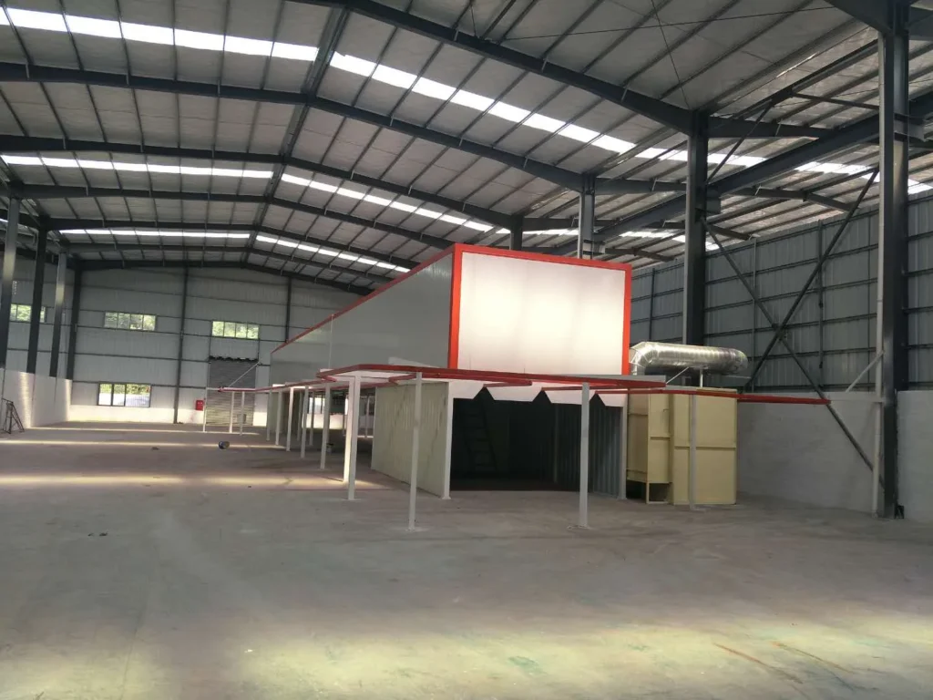
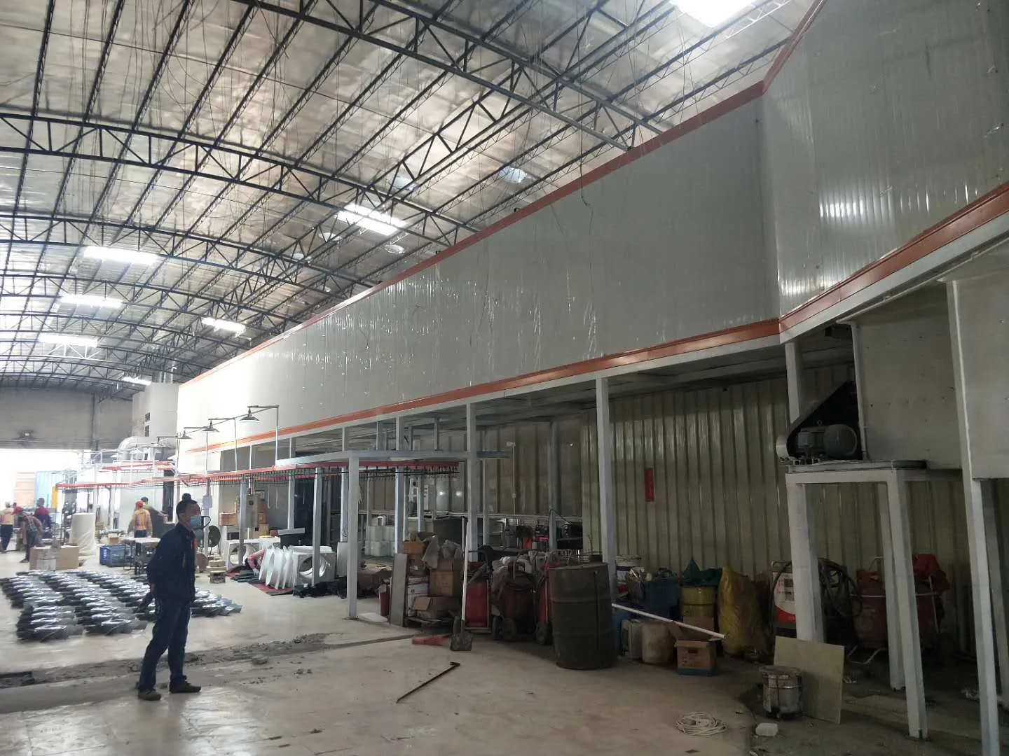
 powder coating line in factory" />
The Critical Role of Curing Temperature Curves in Preventing Cracks
The cure oven isn't just a "bake chamber." It's a precisely calibrated thermal environment where the coating transitions from loose powder particles to a hardened, cross-linked film. Every degree and every minute matters.
Optimal Heating Rate and Holding Time
We recommend controlling the temperature ramp at 5–8°C per minute from ambient to target temperature. This rate allows the coating to heat gradually and uniformly, giving the resin molecules time to flow and orient without creating internal pressure.
Your target cure temperature depends on the powder system—typically 170–200°C for standard epoxy-polyester blends, but check your powder supplier's technical sheet. Once you reach target temperature, hold it for 15–20 minutes to ensure complete cross-linking. Holding too short leaves residual uncured resin, which shrinks excessively later and cracks. Holding too long can overcure and make the coating brittle.
The key is consistency: every workpiece must follow the same temperature profile. In our current projects, we use PLC-controlled ovens with ±5°C tolerance to maintain this precision. Without this level of control, you'll see batch-to-batch variation and intermittent cracking.
Cooling Speed and Its Impact on Stress Relief
After the cure hold, bring the temperature down at no faster than 3°C per minute. This gradual cooling allows the coating to shrink evenly. If you drop temperature too quickly, the surface hardens before the interior can contract, trapping stress.
In one aluminum extrusion project we completed in northern India, the customer initially tried forcing parts into a cold air chamber after the oven. Result: systematic cracking on long profiles. We restructured the line to include a staged cooling section where parts spent 10–15 minutes in a thermally controlled zone before ambient air. Crack rate dropped from ~8% to <0.5%.
Don't rush cooling. It's tempting to speed throughput, but accelerated cooling directly causes cracking. The time you "save" gets spent on rework and customer complaints.
Film Thickness Control: The Most Direct Prevention Strategy
From our work with metal cabinet and furniture manufacturers, we've learned that film thickness is often the easiest variable to control—yet it's where many operators make their biggest mistakes.
Safe Thickness Ranges by Substrate Type
For rigid substrates (steel cabinets, sheet metal parts):
Target 60–80 microns DFT (dry film thickness). This range gives you corrosion protection and durability without excessive shrinkage stress. If you go above 100 microns, you're asking for trouble—thick films shrink more and crack more easily, especially on flat panels where there's no flexing to absorb stress.
For semi-flexible substrates (thin aluminum, bent components):
You can go up to 90–100 microns because the substrate itself has some flex. The workpiece can absorb minor shrinkage stress. But above 100 microns, even flexible substrates struggle.
For complex geometry (deep cabinets with many corners and ridges):
Stay at 60–90 microns maximum. Corners and internal edges are stress concentration points. Thick coating at a corner will crack first.
How to measure and control:
- Use a dry film thickness (DFT) gauge to verify actual thickness, not just spray gun settings
- Measure at least 5 points per workpiece: flat areas, corners, edges, and one recessed area
- If thickness varies by more than 20 microns across one part, adjust spray gun distance or angle
- If 50% or more of your parts exceed target thickness, slow down your spray line speed or reduce spray gun pressure
High-Risk Areas and Thickness Adjustment Principles
Certain geometries are inherently high-risk for cracking, even with correct overall thickness.
Stress concentration zones:
- Sharp internal corners (90° angles where edges meet)
- Edges and perimeters
- Recessed areas
- Weld seams or surface imperfections
In these zones, local thickness should actually be thinner than average, not thicker. This sounds counterintuitive, but it's correct: thin coating at a corner can flex and relieve stress, while thick coating at a corner locks the stress and cracks. If you see cracks always appearing at the same geometric feature (e.g., every corner), your problem is local thickness accumulation there.
Solution:
Adjust spray gun angle or reduce dwell time at high-risk areas. Some automatic spray systems allow zone-based parameter adjustment—this is worth implementing if you run complex-geometry products regularly.
Pre-Treatment Surface Preparation and Its Hidden Impact on Crack Formation
Pre-treatment isn't glamorous, but it's foundational. A poor pre-treatment surface will crack even if your curing and thickness control are perfect.
Phosphate Coating Weight and Surface Roughness
In our experience with offshore projects, we've found that lighter phosphate coatings often outperform heavier ones for crack resistance. Here's why:
Optimal phosphate weight: 10–20 g/m² for steel, 5–10 g/m² for aluminum.
Heavy phosphate (30+ g/m²) creates a thick, brittle conversion layer that itself can crack under thermal stress. It also changes the friction and adhesion profile—sometimes too much adhesion creates a rigid bond that doesn't allow micro-stress relief. Light phosphate, combined with good surface roughness (1.5–3 μm Ra), provides just enough anchor points for powder particles to mechanically interlock without introducing brittleness.
Surface roughness also matters: too smooth and you lose mechanical adhesion; too rough and you trap air pockets that become stress initiation sites. Aim for Ra 1.5–2.5 μm on steel. This is typically achieved by light abrasive blasting or chemical treatment, not by leaving raw material.
Residual Contamination and Moisture Control
After phosphate treatment, you must rinse thoroughly—first with water to remove process salts, then with deionized water to remove dissolved ions. Any residual salt will hygroscopically absorb moisture from humid environments, creating a weak interface under the coating. We've seen this cause delayed cracking weeks after production.
Critical steps post-rinse:
- Dry workpieces completely—surface temperature should reach at least 50–60°C to ensure all moisture has evaporated
- If workpieces sit more than 2 hours between drying and spray application, re-dry them for 10–15 minutes
- In humid climates (>70% RH), consider a final dry-off pass immediately before spray
In one furniture project in Southeast Asia, we discovered that morning humidity was causing workpieces to reabsorb moisture between the dryer and spray booth. Adding a 5-minute intermediate drying station reduced crack complaints by 60%.
Powder Formulation Selection: Matching System Type to Your Substrate
The powder itself—its resin system, cure temperature sensitivity, and flexibility—directly influences crack resistance.
Why Epoxy-Polyester Blends Outperform Pure Polyester for Crack Resistance
Pure polyester powders offer excellent flow and appearance, but they're rigid when cured. Under thermal or mechanical stress, they crack before flexing. They're suitable for high-gloss decorative applications where appearance is paramount.
Epoxy powders are tougher and more flexible, but they can yellow under UV exposure and aren't ideal for outdoor use.
Epoxy-polyester blends are the sweet spot for most industrial applications, especially where durability and crack resistance matter. The epoxy component provides toughness and adhesion; the polyester adds outdoor durability and gloss. The blend typically offers:
- Better flexibility (can absorb some shrinkage stress)
- Lower cracking tendency
- Good adhesion to both steel and aluminum
- Acceptable outdoor performance
Our recommendation: for cabinet, furniture, and extrusion applications, start with a 60/40 or 70/30 epoxy-polyester blend. If crack complaints emerge, before changing your process, first check if you can switch to a blend with higher epoxy content (which increases toughness) rather than trying to fix a formulation problem with process tweaks.
Resin Systems and Cross-Link Density
Cross-link density is the number of chemical bonds between polymer chains. Higher density = stiffer, more brittle. Lower density = more flexible, more elastic.
For crack prevention, you want moderate cross-link density, not maximum. A powder with very high cross-link density will be hard and strong in tension, but it won't absorb shrinkage stress—it'll crack instead. A powder with very low cross-link density will be soft and flexible, but it won't provide durability or chemical resistance.
Practical indicator: Ask your powder supplier for the Shore D hardness of the cured film. Aim for 75–82 Shore D. Below 75, you're too soft; above 82, you're risking brittleness and cracking under stress.
Don't assume more expensive powder is better for your specific problem. A premium powder optimized for outdoor hardness might crack more than a mid-range blend optimized for flexibility. Match the formulation to your actual requirements.
Practical Troubleshooting: Step-by-Step Optimization and Quality Control Checkpoints
If you're currently experiencing crack defects, here's the diagnostic sequence we use in the field.
Week 1: Isolate the Variable
Pick one variable to test, holding everything else constant. This week, focus on cure temperature curve.
- Program your oven for exactly 5°C/min heating, target 200°C, 20-minute hold, 3°C/min cooling
- Run 20 parts
- Inspect for cracks
If cracks drop by 50%+ you've found your culprit. If not, move to Week 2.
Week 2: Verify Film Thickness
Measure DFT on 30 random parts with a calibrated gauge.
- If average is >90 microns, reduce spray gun pressure or increase line speed
- If variation is >25 microns across one part, adjust gun angle or nozzle height
- Run another 20 parts after adjustment
- Re-inspect
Week 3: Check Pre-Treatment
Have your phosphate bath analyzed. Check:
- Phosphate concentration (should be within supplier spec)
- Bath pH
- Contamination level (iron content, dirt)
If out of spec, adjust bath or replace it. Run 20 parts.
Week 4: Evaluate Powder Formulation
If you've ruled out the above, request a trial batch of the same powder with 5–10% higher epoxy content. Run 30 parts. Compare crack rate to your baseline.
This structured approach, done in parallel with your normal production, minimizes disruption and quickly identifies the root cause.
Quality Control Checkpoints
Establish these non-negotiable checks in your daily routine:
| Checkpoint | Measurement | Acceptable Range | Frequency |
|---|---|---|---|
| Oven temperature calibration | Air temp at multiple oven zones | ±5°C of setpoint | Daily |
| Heating ramp rate | Time to reach 200°C from ambient | 20–30 minutes | Daily first shift |
| Pre-treatment phosphate weight | Gravimetric or electronic measurement | 10–20 g/m² (steel) | 3x per week |
| Dry film thickness average | DFT gauge on 10 parts per hour | 60–90 microns | Hourly |
| DFT variation per part | Max thickness minus min thickness | <20 microns | 3x per shift |
| Visual inspection for surface defects | Pre-spray photo standard | Zero oil, salt, dust visible | Every shift |
| Hardness spot check | Shore D gauge, 5 parts per 500-part run | 75–82 | 2x per shift |
| Salt spray test (monthly) | Accelerated corrosion per ASTM B117 | >500 hours to red rust | Monthly on 3 parts |
Track these metrics in a simple spreadsheet or digital log. When crack complaints spike, you'll have data to compare against baseline, which cuts investigation time by 70%.
More Related Questions
What temperature should powder coating be cured at?
Most epoxy-polyester blends cure at 170–200°C. Always verify the exact specification on your powder's technical data sheet, as different formulations have different optimal cure windows. Under-curing (rushing the process) is a common cause of cracking.
Can I repair cracked powder coating?
Limited repair is possible: sand the cracked area, vacuum and wipe clean, re-apply powder to that zone, and re-cure. However, this rarely achieves a perfect match and can create visible seams. Prevention is far more cost-effective than repair.
How does humidity affect powder coating crack risk?
High humidity (>75% RH) during spray application and before cure increases crack risk by allowing moisture absorption into the powder layer. It also affects powder flowability and adhesion. Keep spray booths at 40–65% RH if possible.
Does substrate thickness influence cracking?
Yes. Thicker substrates are more rigid and can accept thicker coatings without flexing. Thin materials (< 1 mm) need thinner coatings and more careful thermal control.
What is the relationship between film thickness and cure time?
Thicker films require longer cure time to achieve full cross-linking in the interior. A 100-micron film needs more time in the oven than a 70-micron film. If you increase thickness without adjusting hold time, you'll under-cure and increase cracking risk.
Conclusion
Powder coating cracks are preventable. They're not random failures or mysterious product defects. They follow a predictable chain of cause and effect: poor pre-treatment, or too-thick film, or improper cure curves, or the wrong powder formulation—often in combination.
From our two decades of experience commissioning and maintaining coating lines across Asia, Africa, and the Middle East, we've learned that the majority of crack problems trace to cure temperature control, not to powder chemistry. Fix your temperature curve first—ramp at 5–8°C per minute, hold at target temperature for 15–20 minutes, cool gradually at <3°C per minute. Then control film thickness to 60–90 microns, verify your pre-treatment is clean and light-phosphated, and match your powder formulation to your actual product needs.
If you're troubleshooting active crack defects, the diagnostic sequence we've outlined will isolate the root cause within 4 weeks. Start with temperature control, then thickness, then pre-treatment, then formulation. Don't skip steps or guess.
For manufacturers in cabinet production, aluminum extrusion, outdoor furniture, and metal fabrication, proper crack prevention isn't a luxury—it's a baseline requirement that separates companies that ship on time from companies that spend their margin on rework.
We at Ketu have helped dozens of manufacturers eliminate chronic cracking issues by applying this framework. Our approach is to install equipment with precise thermal and thickness control, commission it with proper parameter validation, and then support ongoing optimization through regular audits and staff training. If your current coating line is plagued by cracks, or if you're planning a new line and want to avoid these problems from day one, we're equipped to help you design and implement a solution tailored to your products and production environment.
Ready to eliminate crack defects and achieve consistent coating quality? Reach out to discuss your specific production challenge. We can provide recommendations based on your workpiece geometry, desired throughput, and quality targets.
Contact us:
WhatsApp: +8618064668879
Email: ketumachinery@gmail.com