
How to Control Coating Thickness in Powder Dip Tank Coating Lines: Essential Parameters and Adjustment Methods
Coating thickness is one of the most critical variables in electrostatic powder spraying, yet many operators struggle to maintain consistent results. If your line is producing uneven coatings, inconsistent film builds, or quality rejections despite adjusting spray gun settings, the real problem often lies elsewhere—and that's what this guide addresses. From our experience managing powder coating lines across cabinet manufacturing, aluminum extrusion, and furniture production, we've learned that thickness control isn't just about tweaking one parameter. It's about understanding how five major factors work together, and knowing where to look when things go wrong.
Coating thickness in electrostatic powder spraying is controlled primarily by five key factors: spray gun voltage and distance, powder supply rate, conveyor speed, and workpiece grounding quality. Adjusting these parameters in coordination—such as reducing line speed to extend spray dwell time, increasing voltage within safe limits for better powder adhesion, or fine-tuning powder flow to match transfer efficiency—ensures uniform film thickness across workpieces. Pre-treatment quality, compressed air purity, and curing temperature stability also influence final thickness. Regular measurement with a dry film thickness gauge and systematic parameter checks help maintain consistent coatings within specification.
Let me walk you through the practical methodology we use on our production lines, starting with what really matters and working down to the specific diagnostic steps that solve problems most shops face.
What Factors Affect Coating Thickness in Powder Dip Tank Systems
Before you touch a single parameter, understand that thickness isn't determined by one thing—it's the result of a chain. Break any link, and your coating suffers.
Pre-treatment Quality and Surface Condition
This is where most thickness problems actually originate. I can't stress this enough: a poor pre-treatment surface doesn't just cause adhesion issues—it destroys thickness uniformity.
If your workpiece arrives at the spray booth with oil film, water residue, salt deposits, or oxidation still present, the electrostatic field doesn't work the way you planned. The powder won't sit evenly because the electrostatic attraction isn't uniform. What you see is thicker deposits in some areas and thin spots in others, even though the spray gun parameters stayed the same.
We've diagnosed countless "thickness variation" complaints where the real culprit was dried water spots on the workpiece surface or incomplete rinsing after the phosphate stage. The workpiece looks dry to the eye, but microscopic moisture or salt crystals are still there. When the high-voltage electrostatic field hits that surface, the charge distribution becomes irregular, and powder migration patterns become chaotic.
Our standard pre-treatment check includes:
- Full degreasing with proper alkaline chemistry and dwell time
- Complete rinse stages with at least two cascading rinse tanks
- Phosphate conversion or chromium-free treatment applied consistently
- Pure water final rinse to remove salts
- Thorough drying, verified by touch and surface temperature
- No delay between drying and spraying (ideally less than 2 minutes)
![electrostatic powder coating line in factory]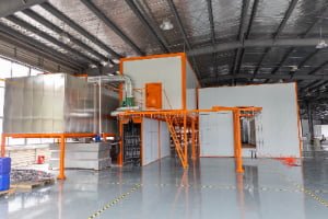
Spray Gun Parameters (Voltage, Distance, Powder Supply)
Once pre-treatment is locked in, your three active controls are voltage, distance, and powder flow.
Voltage determines how strongly the powder particles are attracted to the workpiece. Low voltage means weak attraction—particles don't travel efficiently, and most fall short of the target. You get thin, inconsistent coating. Higher voltage improves transfer efficiency up to a point, but push it too far and you risk back-ionization, where powder bounces off the workpiece instead of sticking. Most industrial applications run between 60–90 kV, but the sweet spot for your specific powder and workpiece geometry requires testing.
Distance from gun to workpiece controls the charge and velocity of the powder cloud. Too close (under 150mm for most standard guns), and you concentrate the powder too densely—you get thick spots, sagging, and powder accumulation at edges. Too far (over 300mm), and the powder disperses before reaching the surface—upper areas receive less coating, edge coverage weakens, and you waste powder.
Powder supply rate must match the air velocity and gun geometry. If you pump too much powder into the air stream, it overwhelms the air's carrying capacity—powder falls, clogs the lines, and you get puddles. Too little, and you're not utilizing your spray time efficiently.
The key insight: these three work together. Increasing voltage without adjusting distance can overshoot your target thickness and cause edge banding. Increasing powder supply without adjusting line speed leads to overapplication and rework.
Conveyor Speed and Dwell Time
Line speed is the great hidden thickness controller that many operators overlook. Slower line speed means workpieces spend more time in the spray booth under the gun—longer dwell time accumulates more powder, resulting in thicker coating. Faster line speed delivers less spray time, producing thinner coatings.
We've observed that a 20% increase in line speed typically reduces coating thickness by 15–25%, depending on powder characteristics and gun configuration.
The challenge is that line speed affects the entire production rhythm. You can't just slow down one section without backing up inventory. So thickness is usually managed by line speed as a last resort, not a first adjustment. It's better controlled through powder supply and voltage before you touch conveyor speed.
But here's what matters for consistency: the conveyor speed must be absolutely stable. If your chain jerks, hesitates, or varies by ±5%, your coating thickness will vary proportionally. Workpieces that linger get thicker coatings; those that rush get thinner. This is one of the most common causes of thickness banding in production.
Compressed Air Quality and System Stability
Poor compressed air ruins everything. Air that contains water droplets, oil mist, or fine particulates corrupts the powder flow, destabilizes the charge transfer, and creates surface defects that make thickness measurement unreliable.
Water in the air causes two problems: (1) it condenses on the powder particles, making them clump and difficult to disperse evenly, and (2) it lands on the workpiece surface just before the powder arrives, creating micro-puddles that disrupt adhesion and thickness uniformity. Oil mist does something worse—it can actually create a barrier that prevents powder from bonding, resulting in apparent thin spots where the powder actually sits on top of the oil film instead of adhering to the substrate.
We mandate regular compressed air testing and maintenance: install a dryer upstream of the spray system, use multi-stage filtration (particulate, oil removal, and secondary particulate), and drain the system daily. A simple pressure gauge and desiccant indicator cartridge in the air supply line is worth the small cost—it prevents hours of troubleshooting.
How to Match Conveyor Speed with Powder Supply for Consistent Thickness
Here's where coordination becomes critical. Imagine your line speed suddenly increased from 5 meters/minute to 6 meters/minute. The workpiece now spends 17% less time under the spray gun. If you don't adjust powder supply upward by approximately the same percentage, your coating drops below target thickness—thinner, more inconsistent, and potentially rejected.
The relationship isn't perfectly linear because:
- At very low line speeds, the powder has time to settle unevenly, creating thickness banding
- At very high speeds, the powder cloud doesn't fully develop in time, and you lose efficiency
- Powder supply curves aren't perfectly proportional to dwell time
Our approach is to establish a baseline configuration at your standard line speed with your current powder formulation. Then we plot thickness against both line speed and powder supply changes. This creates a reference matrix. When you need to adjust production speed, you've already calculated what powder supply change is required.
For example: If your baseline is 5 m/min line speed with 2.5 kg/min powder supply producing 80 microns average thickness, and you increase to 6 m/min, you might need to increase powder supply to 2.85 kg/min to maintain that 80 micron target. But you won't know your exact number until you measure and verify on your specific line with your specific powder.
The reason we emphasize this: chasing thickness by constantly tweaking one thing at a time without understanding their relationship is exhausting. You adjust voltage, thickness improves, then the next day it drifts again because humidity changed or line speed micro-drifted. Establishing these baseline relationships means you diagnose faster and adjust with confidence.
The Three-Parameter Balance: Voltage, Line Speed, and Powder Feed Rate
I want to be explicit about how these three interact, because most operators understand them individually but miss the interdependency.
| Parameter | Effect on Thickness | Adjustment Trigger | Typical Range |
|---|---|---|---|
| Voltage (kV) | Increases powder transfer efficiency; higher voltage = stronger attraction to workpiece | Thickness thin + powder recovery poor | 60–90 kV |
| Powder Feed Rate (kg/min) | Direct correlation; more powder = thicker coating | Thickness below target after confirming line speed stable | 2–4 kg/min (typical) |
| Line Speed (m/min) | Inverse relationship; slower speed = longer dwell = thicker coating | Need to increase throughput without sacrificing thickness | 3–8 m/min (variable by product) |
When you adjust one, the others may need recalibration. For example:
Scenario 1: Thickness is consistently 10 microns below target.
- Check pre-treatment and grounding first (confirms substrate is ready)
- Increase voltage by 5 kV and measure (if transfer efficiency is the issue, this helps)
- If voltage is already at 85 kV, increase powder supply by 0.3 kg/min instead
- If line speed is the variable, reduce it by 0.5 m/min and verify impact
Scenario 2: Thickness is good on average, but varies by ±8 microns across the batch.
- This usually indicates instability in line speed, not a parameter setting problem
- Check conveyor chain tension, sprocket alignment, and speed controller calibration
- Verify compressed air pressure stability (should vary less than ±0.5 bar during spray cycle)
Scenario 3: Thickness at one end is 85 microns; other end is 72 microns.
- Check workpiece grounding and contact point quality (one side may be loose or corroded)
- Verify spray gun positioning and angle consistency
- Measure air velocity at different booth locations (can reveal exhaust imbalance)
The practical golden rule we follow: never adjust more than one parameter at a time, and always wait 10 minutes and measure 5 parts before declaring the change successful. Powder coating systems have inertia—changes don't show up instantly, and hasty re-adjustments often overcorrect.
Pre-treatment and Grounding: Why They Matter More Than You Think
I want to hammer this home because it's the most overlooked factor in thickness consistency. Pre-treatment and grounding are foundational. Everything else is tuning.
Pre-treatment creates two things: (1) a chemically active surface that powder particles can cling to permanently, and (2) a consistent surface profile (usually 1–3 microns of micro-roughness) that the powder can mechanically grip. Without this, no amount of voltage or powder supply will create a durable, uniform coating.
When pre-treatment is compromised—say, the phosphate tank is depleted, or rinse water is getting recycled too many times and accumulating contaminants—the powder deposits unevenly. You'll see patterns: thicker near entry points to the spray booth, thinner in corners, inconsistent banding. The spray parameters look perfect, but the substrate is rejecting the powder.
Grounding is the electrical circuit that completes the attraction. The workpiece must be reliably connected to ground so the electrostatic field can function. A single point of contact that's loose, corroded, or contaminated with powder residue breaks this circuit locally. That section of the workpiece won't receive powder evenly—or at all.
We've diagnosed "mysterious" thickness failures where the culprit was a corroded contact point on the hanging rack. The workpiece looked fine to the operator, but electrical continuity was terrible. The solution: clean the contact point, verify resistance with a multimeter (should be under 1 ohm), and test again.
The bottom line: spend 5 minutes verifying pre-treatment chemistry and grounding integrity before you spend an hour adjusting spray gun dials.
How to Measure and Verify Coating Thickness Correctly
Measurement is where your numbers become real. If you're measuring wrong, all your adjustments are guesses.
Using Dry Film Thickness Gauges
A dry film thickness (DFT) gauge is non-destructive, fast, and reliable when used correctly. It works by measuring the gap between the substrate and a magnetic or eddy-current probe. Most industrial powder coating uses ferrous substrates (steel), so magnetic gauges are standard.
Proper measurement technique:
- Calibrate the gauge daily on a zero plate (usually provided by the manufacturer)
- Take measurements on representative parts—not just the first piece off the line
- Record at least 3 points per part: one central location, and two toward the edges
- Average the readings; don't rely on a single spot
- Understand your tolerance band (e.g., 80±10 microns means acceptable range is 70–90 microns)
Common measurement mistakes we see:
- Measuring only one location per part (misses thickness variation)
- Measuring too close to sharp edges or corners (readings are artificially high there)
- Not accounting for substrate surface roughness (some gauges are sensitive to it)
- Failing to calibrate regularly (drift is silent but deadly)
From our experience, the most accurate approach is to measure 10 parts randomly selected from each production run, record all data, and plot it. This reveals trends much faster than spot-checking. If thickness is drifting upward, you catch it before it goes out of spec. If it's suddenly erratic, you investigate the root cause (usually a line speed issue or grounding problem) instead of guessing.
Beyond Numbers: Adhesion Testing and Performance Validation
Here's what many operators miss: a coating can measure exactly 80 microns and still fail in the field if adhesion is poor. Thickness alone doesn't guarantee performance.
We run adhesion tests routinely:
- Cross-hatch test (ASTM D3359): Apply adhesive tape over a crosshatch pattern cut into the coating, then peel. If coating flakes off, adhesion is failing.
- Impact test (ASTM D2794): Strike the back of a coated part with a calibrated impact tool. Measure the reverse and obverse sides for cracking or delamination.
- Salt spray test (ASTM B117): For critical parts requiring corrosion resistance, especially in cabinet and outdoor furniture applications. This is the real-world proof—parts sit in a saltwater fog chamber for 500–1000 hours. If coating adheres and substrate shows no creepage, you're good.
The reason we emphasize this: sometimes thickness variation is actually acceptable if adhesion is strong and the workpiece performs well in its application. But if adhesion is marginal, even perfect thickness won't save you. So measure thickness and verify adhesion on a regular schedule.
Troubleshooting Common Coating Thickness Problems: Diagnosis and Solutions
When thickness goes wrong, the root cause is usually one of three categories. We use this diagnostic sequence:
Thickness Variations Across Different Areas
Problem: Edge areas are thicker; center areas are thinner. Or one side of the workpiece is visibly thicker than the other.
Most likely causes:
-
Uneven grounding — One contact point on the hanging rack is loose or corroded. The weakly grounded side receives less powder.
- Solution: Inspect all contact points. Clean with a wire brush or mild abrasive. Verify resistance with a multimeter (should be <1 ohm).
-
Spray gun positioning inconsistency — Gun is angled off-perpendicular, or gun nozzles are at different distances from the workpiece.
- Solution: Re-level the gun mounting. Measure distances at multiple points. Adjust gun holder or articulating arm as needed.
-
Workpiece geometry blocking powder — Deep recesses, internal corners, or narrow slots aren't receiving spray because of line-of-sight issues (Faraday cage effect).
- Solution: Rotate workpiece orientation on rack. Add second spray position or angle. Lower voltage slightly and increase powder supply to help powder penetrate recesses.
Coating Too Thin or Too Thick
Problem: All measurements are consistently below or above target, and the issue isn't related to one area of the workpiece.
If thickness is consistently thin:
- Check pre-treatment (if compromised, powder won't adhere efficiently)
- Verify grounding on a few parts (use multimeter if unsure)
- Increase voltage by 5 kV (if not already at maximum safe level ~90 kV)
- Increase powder supply rate by 0.2–0.3 kg/min
- Reduce line speed by 0.5 m/min if thickness still below target
- Check compressed air pressure—low pressure reduces powder atomization quality
If thickness is consistently thick:
- Verify line speed is stable (check speed controller display)
- Reduce powder supply rate by 0.2 kg/min
- Reduce voltage by 5 kV (lower voltage = less efficient transfer = less thickness accumulation)
- Increase line speed by 0.5 m/min if needed (but this is a last resort due to throughput impact)
- Check for powder bridging in supply lines (blockage can cause intermittent over-supply)
Adhesion Issues Despite Correct Thickness Readings
Problem: Thickness gauge shows 80 microns, spec is 80±10, everything looks good—but adhesion test fails or field complaints occur.
This is often a hidden pre-treatment problem. Thickness and adhesion are two separate things.
Most likely causes:
-
Inadequate pre-treatment chemistry — Phosphate tank is depleted, rinse water is contaminated, or drying was incomplete.
- Solution: Replace phosphate bath according to supplier guidelines. Refresh rinse tanks. Verify drying temperature and time. Run adhesion test on a known-good part prepared with fresh chemistry; compare results.
-
Curing temperature or time insufficient — Powder appears to be cured (hard to touch), but cross-linking isn't complete.
- Solution: Measure actual workpiece temperature (use IR thermometer) as it exits the curing oven. Verify it matches powder supplier's required temperature. Extend dwell time in oven if necessary.
-
Contaminated compressed air — Water or oil in air creates micro-adhesion failures.
- Solution: Test air quality (pressure, dew point, particle count). Install or service drier and filters. Bleed water from compressor tank daily.
-
Incompatible powder or resin system — Wrong powder for substrate or environmental requirement.
- Solution: Confirm powder specification matches the application. For cabinet work, use epoxy or polyester for corrosion resistance. For outdoor furniture, use polyester or polyurethane for UV/weather resistance. Run salt spray or outdoor exposure test on sample coating.
How to Set Thickness Standards Based on Product Type and Application Requirements
Not all products need the same coating thickness. Thickness specifications should match the product's actual performance requirements, not some generic industry standard.
Cabinet and Enclosure Products (Electrical, Telecom, etc.):
- Typical spec: 80–100 microns
- Rationale: These face frequent handling, potential scratches, and need strong corrosion resistance. Thicker coating provides durability buffer.
- Curing requirement: 170–200°C for 10–20 minutes (depending on powder chemistry)
- Testing: Salt spray minimum 500 hours; adhesion per ASTM D3359
Outdoor Furniture (Aluminum or Steel):
- Typical spec: 70–90 microns
- Rationale: Lower than enclosures because the finish is primarily aesthetic. Needs UV/weather resistance more than extreme durability.
- Curing requirement: 200–220°C for 8–15 minutes (polyester or polyurethane powder)
- Testing: QUV accelerated weathering (ASTM G154) minimum 1000 hours; adhesion test
Aluminum Extrusion and Precision Components:
- Typical spec: 60–80 microns
- Rationale: Too-thick coating can interfere with assembly tolerances, especially if components fit into slots or stack tightly. Thinner coating is acceptable because aluminum itself resists corrosion better than bare steel.
- Curing requirement: 200–230°C, 10–20 minutes depending on alloy conductivity
- Testing: Adhesion per ASTM D3359; dimensional check post-coating
Metal Racks, Shelving (Utility Storage):
- Typical spec: 50–70 microns
- Rationale: Lower performance requirement; primary goal is basic appearance and minimal rust prevention. Thicker coating isn't necessary and increases cost.
- Curing requirement: 170–200°C, 10–15 minutes
- Testing: Basic adhesion; visual inspection for coverage
The key insight: set your thickness spec based on the product's end-use environment and required performance, not on what you think "looks thick enough." A cabinet destined for harsh salt-spray environments needs 100+ microns. A decorator shelf indoors can succeed at 60 microns.
Once you've set your spec for each product type, communicate it clearly to production—and stick to it. If you're constantly adjusting thickness targets, you're fighting against instability upstream (pre-treatment, grounding, air quality, line speed).
![aluminum profile surface finishing]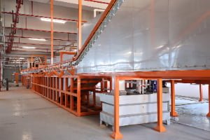
Real-World Implementation: A Practical Checklist for Stable Thickness Control
Based on hundreds of production lines we've commissioned, here's the sequence we follow to lock in thickness stability:
Week 1: Baseline Establishment
- Verify pre-treatment tank chemistries (pH, concentration, temperature)
- Clean all contact points on hanging racks; test electrical resistance
- Calibrate DFT gauge; measure 20 parts from current production
- Record line speed, powder supply rate, voltage, distance
- Plot thickness data; identify current mean and standard deviation
Week 2: Parameter Optimization
- Adjust line speed to your target throughput (e.g., 5 m/min)
- Set voltage to middle-safe range (typically 75 kV for most powders)
- Adjust powder supply to achieve target thickness (usually requires 2–3 test runs)
- Measure 10 parts; record mean thickness
- Calculate standard deviation; if >5 microns, investigate cause (usually grounding or line speed instability)
Week 3: Stabilization & Documentation
- Run 50-part production batch; measure every 10th part
- Plot data to confirm consistency (should show tight clustering)
- Document final settings: voltage, powder supply, line speed, air pressure, drying time
- Run adhesion test on random sample
- Create a laminated reference card for operators
Ongoing (Monthly):
- Recalibrate DFT gauge
- Sample measure 10 parts; compare against baseline
- Inspect pre-treatment bath (pH, concentration, appearance)
- Clean contact points on racks
- Check compressed air drier cartridge; replace if needed
The reason this works: you're not chasing daily micro-adjustments. You've locked in the fundamentals (pre-treatment, grounding, air quality, line stability) and documented the three active parameters (voltage, powder supply, line speed) that produce your target thickness. When something drifts, you check the fundamentals first, then adjust parameters if needed.
More Related Questions
Q: Should we adjust spray gun distance if thickness is uneven?
A: Yes, but after verifying grounding first. If one section is thicker, check if that section's ground contact is loose. If the entire workpiece is uneven edge-to-edge, gun distance may be off. Move the gun closer (increases thickness) or further (decreases thickness) by 10mm increments and measure again.
Q: Can we use a single thickness measurement per part?
A: Not reliably. Always measure at minimum 3 locations per part. Powder coating varies across the surface due to geometry, gun angle, and electrostatic field shape. A single reading can be misleading—you might catch one thick spot and miss a thin spot elsewhere.
Q: What's the impact of humidity on coating thickness?
A: High humidity affects powder flow and adhesion, not directly the thickness reading itself. However, humid air reduces powder flow quality, which can make powder supply less predictable. Keep spray booth humidity below 60% if possible. If humidity is high, slightly increase drying time in pre-treatment and verify compressed air dryness.
Q: How often should we replace the phosphate bath?
A: Check pH daily and concentration weekly. Replace when pH drifts below specification (usually pH 3–4 depending on formulation) or concentration drops below 50% of recommended level. Typical replacement interval is every 3–6 months depending on part load and water quality.
Q: Is higher voltage always better for thickness?
A: No. Voltage controls transfer efficiency, not thickness directly. Too-high voltage (>90 kV) risks back-ionization and bouncing powder. The right voltage maximizes transfer efficiency, allowing you to achieve target thickness with lower powder waste. Find the optimal voltage through testing (usually 70–85 kV for most applications), then control thickness via powder supply and line speed.
Conclusion
Coating thickness control is not a mystery. It's a system with five primary inputs (pre-treatment, grounding, voltage, powder supply, line speed) and three secondary inputs (compressed air quality, dwell time stability, curing parameters). When thickness goes wrong, the root cause is almost always instability in one of these areas.
The operators we work with who have the tightest thickness control (±3 microns consistently) aren't twiddling parameters daily. They've verified their fundamentals once, locked in their settings, and only adjust when production requirements change. They measure regularly but interpret data systematically—looking for drift trends, not panicking over single-part variance.
If you're struggling with thickness consistency right now, start here: verify pre-treatment chemistry, clean and test grounding, measure 10 parts, document your findings, and then adjust active parameters. You'll solve 80% of thickness problems without touching a spray gun setting.
If you're ready to optimize your entire line for better thickness control—whether you're running cabinet production, furniture coating, or aluminum extrusion work—we'd like to discuss your specific setup. We've customized thickness control strategies for operations spanning different product types, production volumes, and automation levels. Our team can help you establish baseline parameters, train operators on measurement and diagnostics, and implement monitoring systems that prevent drift before it becomes a problem.
Get in touch: WhatsApp +8618064668879 or email ketumachinery@gmail.com. We're here to help you lock in reliable thickness and reduce rework.