How to Build a Powder Coating Oven: Complete System Design and Selection Guide
Building an effective powder coating oven is far more than assembling a heating chamber. It's about creating a complete thermal system that ensures uniform coating cure, safe operation, and long-term reliability. Whether you're designing a new spray line, upgrading an existing one, or evaluating equipment options, understanding the core principles of oven construction will help you make better decisions.
What Is a Powder Coating Oven & Why You Need One
A powder coating oven is a specialized heating chamber designed to cure powdered coatings on metal workpieces through controlled thermal processing. It's not simply a generic industrial oven—it's engineered specifically to meet the unique demands of powder coating applications.
When powder particles are electrostatically applied to a grounded workpiece, they sit on the surface with relatively weak adhesion. The curing oven transforms this temporary coating into a durable, permanent finish through a chemical process that requires precise temperature control, uniform heat distribution, and adequate dwell time.
We've observed that many manufacturing operations attempt to use standard industrial ovens or adapt equipment not designed for powder coating. This approach consistently leads to problems: color inconsistency, poor adhesion, surface defects, and wasted material. A properly designed powder coating oven eliminates these issues.
Powder Coating vs. Traditional Finishing Methods
Powder coating offers distinct advantages over liquid paint systems. The application rate is faster, material waste is dramatically lower (up to 95% recapture of unused powder), and the coating provides superior durability and consistency. However, these benefits depend entirely on having a curing oven that maintains precise temperature uniformity.
Unlike solvent-based paint, which hardens primarily through evaporation, powder coating cures through thermally-induced chemical cross-linking. This means the oven doesn't just need to be hot—it needs to be consistently hot across every part of the chamber. A 20°C temperature difference between the top and bottom of your oven chamber will produce noticeably different coating hardness, gloss, and adhesion.

DIY vs. Commercial Ovens: Cost & Performance Comparison
We frequently encounter manufacturers weighing the decision to build a custom oven versus purchasing a pre-manufactured unit. This decision ultimately depends on your production volume, available capital, technical expertise, and timeline.
DIY Construction: Building an oven from components (framework, insulation, heating elements, controls) can cost between $1,200–$3,500 depending on size. You gain flexibility in customization but face risks in thermal uniformity, longevity, and compliance with local safety standards. The learning curve for achieving proper insulation, air distribution, and temperature control is steep.
Commercial Units: Pre-engineered ovens cost more ($8,000–$50,000+) but come with proven thermal performance, manufacturer support, warranty coverage, and compliance documentation. For any production operation running more than 10–15 hours per week, the reliability and consistency of a commercial unit typically justify the investment.
Our recommendation: unless you have strong fabrication experience and limited throughput, invest in a commercial unit designed for powder coating. The cost premium is recovered through reduced material waste, fewer quality failures, and lower operational downtime.
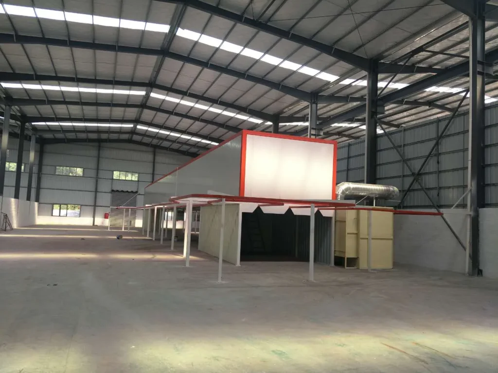
Core Components & Systems of a Powder Coating Oven
A functional powder coating oven comprises four interdependent systems. Poor integration between any of these will compromise overall performance.
Frame & Structure (Riveted Steel Construction)
The oven chamber begins with a steel frame. Standard construction uses either welded or riveted 40×60mm or 100×100mm steel tubing, depending on oven dimensions and expected thermal stress.
Riveted construction is common in field-assembled units because it allows disassembly for relocation or modification. Welded frames are typically found in factory-built units where structural permanence is desired.
The frame must support:
- The weight of insulation and outer casing
- The thermal expansion stresses from heating and cooling cycles
- Continuous vibration from air circulation fans
- The static load of workpieces being conveyed through the chamber
From our experience working with cabinet makers and furniture manufacturers, undersized or improperly braced frames lead to warping over 6–12 months of continuous use. We recommend 150×150mm steel plate footings spaced every 1–2 meters to distribute floor loads evenly.
Heating System (Electric, Gas & Fuel Options)
This is where your operating cost model begins. The choice between electric and gas heating depends on production volume, energy availability, and budget structure.
Electric heating uses stainless steel resistance tubes, typically 1–3kW each depending on total chamber size. Heating elements are mounted directly in the airflow path. Air entering at ambient temperature can reach target cure temperature (typically 200°C) in 30–40 minutes when cold-starting.
Advantages: precise temperature control via thermostats, minimal maintenance, instant shutdown capability, no combustion risk, safer for operators.
Disadvantages: higher per-unit energy cost, slower warm-up time, requires robust electrical infrastructure (often 380V 3-phase, 50–100A depending on kW demand).
Best suited for: small-to-medium production (<20 pieces/hour), frequent color changes, R&D or job-shop operations.
Gas heating (natural gas or LPG) uses a burner to heat air directly; hot air is then distributed via circulation fan. The chamber can warm to 200°C in 15–20 minutes.
Advantages: lower per-unit energy cost, faster warm-up, excellent for continuous high-volume production.
Disadvantages: requires gas supply infrastructure, needs regular burner maintenance and calibration, proportional valve adds complexity, slight risk of incomplete combustion if not tuned properly.
Best suited for: high-volume continuous production (>50 pieces/hour), stable product runs, where per-piece energy cost matters most.
Our practice-based observation: We've seen many small operations choose gas to reduce operating costs, only to discover that gas supply variability or burner drift causes temperature swings that ruin coating quality. Electric heating, though costlier to run, tends to deliver more consistent curing results in real-world field conditions.
Convection & Air Circulation System
Forced-air circulation is the single most important factor in achieving uniform temperature distribution inside the oven chamber. Without it, heat stratifies—the top of the chamber runs hotter than the bottom, and corners remain cooler than the center.
A typical system includes:
- Circulation fan (1.5–3.0kW depending on chamber volume)
- Supply air slots (distributed along top or sides of chamber)
- Return air chamber (below the workpiece path)
- Ducting to recirculate heated air multiple times per minute
The circulation fan draws cooler air from the return chamber, forces it through or around the heating elements, and distributes the heated air back into the chamber through slots or perforated ducting. This continuous recirculation flattens temperature gradients.
We recommend air changes of at least 3–4 complete chamber volumes per minute. For a chamber measuring 5m × 2m × 2m (20 cubic meters), you'd want circulation of 60–80 m³/min. Underpowered fans lead to hot spots and cold zones; oversized fans waste energy and can cause excessive turbulence.
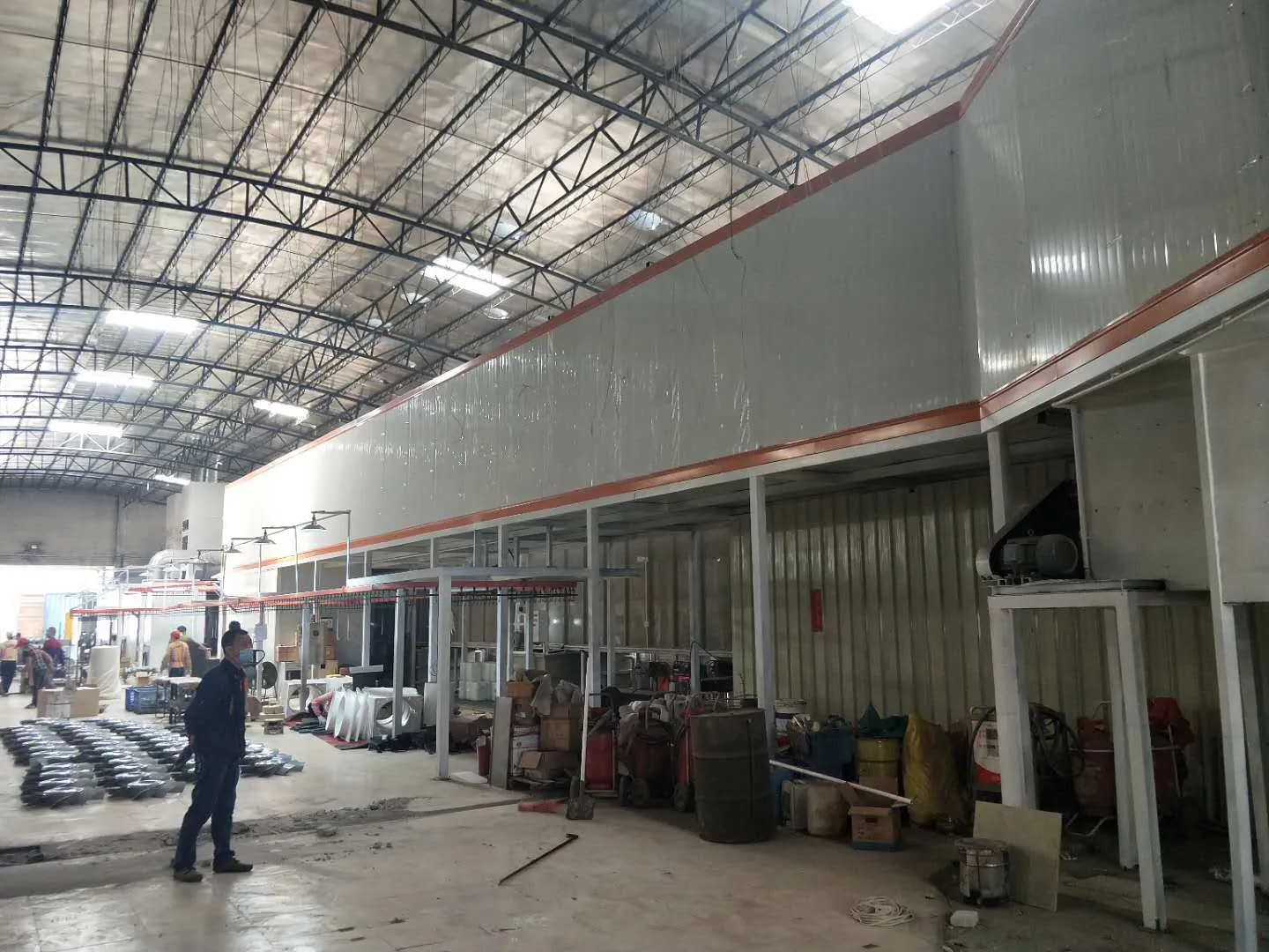
Insulation & Outer Casing
The insulation layer determines your oven's energy efficiency and operator safety. The outer casing protects the insulation and provides a professional appearance.
Insulation Material: Rockwool (mineral fiber) with an R-value of 0.04–0.06 W/m·K is standard. Thickness typically ranges from 80–150mm depending on ambient conditions and desired exterior surface temperature.
A 100mm rockwool layer with proper sealing keeps the outer surface at only 10–15°C above ambient—critical for worker safety and to prevent thermal stress on nearby equipment.
Casing: The outer layer is typically 0.6–0.8mm galvanized or colored steel sheet, riveted or bolted to the frame. This protects insulation from physical damage and moisture ingress.
Sealing: High-temperature silicone sealant is applied at all seams, gaps, and interfaces. This is often overlooked but essential. Any air leakage bypasses the heating chamber, reducing efficiency and creating temperature inconsistencies. We use high-temperature gaskets rated to at least 300°C.
Interior Protection: The inner surface (facing the chamber) is typically 0.8–1.0mm galvanized or mild steel sheet. This protects the insulation from dust, powder residue, and thermal shock, extending the life of the insulation layer significantly.
Designing Your Oven: Size, Capacity & Heating Power
Calculating Interior Dimensions Based on Workpiece Size
The chamber dimensions must accommodate your largest workpiece plus clearance for air circulation and handling.
If your largest piece is 1500mm long × 1100mm wide × 1200mm tall, the chamber interior should be:
- Length: 1500mm + 200mm clearance = 1700mm minimum (typically round up to 1800–2000mm for air distribution room)
- Width: 1100mm + 150mm clearance = 1250mm minimum
- Height: 1200mm + 300mm clearance = 1500mm minimum
The extra clearance allows air to circulate evenly around the workpiece without creating dead zones or hot spots. Undersized chambers force air into high-velocity jets that cause uneven heating.
For cabinet makers (our primary customer base), chamber length is typically 4–6 meters to accommodate conveyors, with height and width sized to fit the product range. For aluminum extrusion producers, chamber dimensions often reflect the need for continuous or rapid batch processing, requiring larger volumes and higher throughput rates.
Determining Heating Wattage (100-150W per Cubic Foot)
This is where sizing becomes precise. Insufficient heating wattage means slow warm-up, temperature sag under load, and inconsistent curing. Excessive wattage wastes energy and risks thermal overshooting.
Standard formula: 100–150 watts per cubic foot of chamber volume.
For a chamber measuring 5m × 2m × 2m:
- Volume = 20 cubic meters = ~706 cubic feet
- Required heating power = 706 × 100–150W = 70,600–105,900W (71–106 kW)
This assumes electric heating. For gas heating, burner output is typically rated in BTU/hour. Use an online BTU-to-wattage converter or ask your gas equipment supplier.
The higher end (150W/ft³) is appropriate for:
- Ovens with poor insulation
- High ambient temperatures (outdoor installations)
- Frequent cold starts
- Very large workpieces that sink internal temperature rapidly
The lower end (100W/ft³) works for:
- Well-insulated ovens
- Continuous production with minimal cold-starts
- Smaller, faster-cycling operations
From our experience, we typically design for 120–130W/ft³ to balance energy cost with operational flexibility.
Material Selection & Cost Considerations (Steel Gauge, Galvanized Coating)
Frame material: Q235 mild steel is standard for the structural frame. Gauge thickness typically ranges from 1.5–2.5mm depending on span and load. Larger ovens (>6m length) may require 3mm or heavier to prevent sagging.
Cost roughly correlates with weight and complexity:
- Small electric oven (2m × 1.5m × 1.5m): $1,200–$2,500
- Medium gas oven (4m × 2m × 2m): $5,000–$12,000
- Large custom industrial oven (6m × 3m × 2.5m): $15,000–$40,000+
Galvanized vs. painted casing: galvanized steel costs 15–20% more but requires no maintenance. Painted steel is cheaper but needs repainting every 3–5 years if exposed to weather or humid environments. For continuous operation, galvanized is more economical over the oven's lifetime.
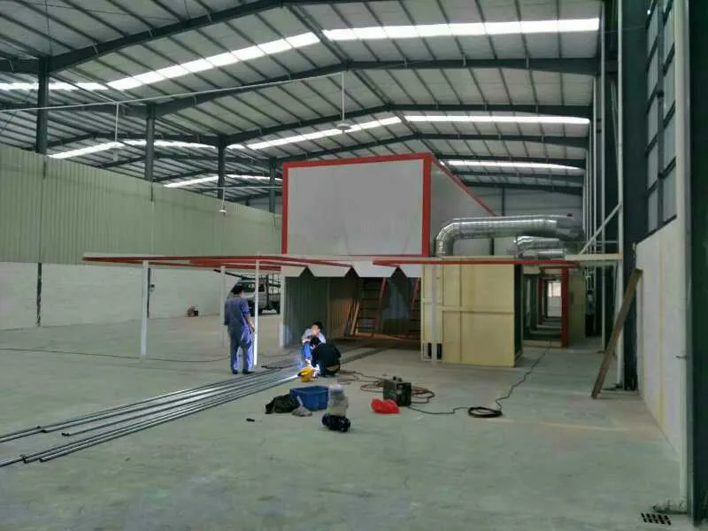
Step-by-Step Construction: Materials, Tools & Assembly
Steel Frame & Rivet Connection Method
Begin by laying out the base frame on a level surface. Use 40×60mm or larger steel tubing depending on your span.
Cut and position the longitudinal beams (the long sides of your frame). These carry the primary structural load. Use angle iron or structural angle to brace corners and prevent racking (twisting).
Position vertical uprights at 1–1.5m intervals. These support the insulation and casing weight. Space them closer if the casing is thin or if wind loading is a concern.
Riveting: Use a pneumatic rivet gun rated for your rivet size (typically 1/8" or 3/16"). Drill rivet holes slightly larger than the rivet diameter. Insert rivets and fire them with rapid hammer strikes until fully seated. A properly set rivet creates a permanent, vibration-resistant joint.
Alternative (welding): If you have welding equipment, mild steel frames can be MIG or stick welded. Welds provide slightly more structural integrity but are less flexible for field disassembly.
Inspect all connections. Loose rivets or welds will vibrate and stress joints during operation.
Floor Design (With/Without Integrated Floor)
Option 1 – Integrated Floor: Fabricate the floor as part of the frame using 1.5–2.0mm steel plate. This floor sits inside the frame perimeter and supports the weight of workpieces plus any accumulating dust and insulation particles.
Advantages: simpler assembly, floor is integrated, good for cleanliness.
Disadvantages: makes the oven heavier, complicates relocation, dust accumulates on the floor and must be periodically swept.
Option 2 – Open Floor (No Integrated Floor): The frame has no internal floor; workpieces are conveyed on an external chain or roller. Air circulates freely underneath, improving uniformity.
Advantages: lighter overall weight, easier air circulation, less accumulated dust.
Disadvantages: workpieces must be supported externally (requires compatible conveyor system), more complex to seal the bottom.
Our recommendation: for cabinet and furniture applications, an integrated floor with drainage is preferable. For high-volume extrusion processing, an open floor works better.
If you include an integrated floor, slope it slightly (1–2%) toward a drain outlet to allow condensation and dust to exit. Include a removable grate or cleanout cover for maintenance access.
Steel Facing & Sealing
Once the frame is complete, attach the inner steel facing (0.8–1.0mm sheet) to all interior surfaces. This protects the insulation and provides a smooth, cleanable interior.
Use pneumatic rivets spaced ~150mm apart around all edges and seams. The facing should be taut but not overstressed—leave slightly more than zero tension to allow for thermal movement.
Apply high-temperature silicone sealant (rated to 300°C minimum) to all seams where the facing sheets join. Pay special attention to:
- All internal corners
- Gaps around any interior penetrations (heating element mounts, thermocouple ports)
- The joint where the floor meets the walls
Sealant is your primary defense against air leakage. A poorly sealed chamber will have temperature swings and energy waste proportional to the leakage area.
After the sealant cures (typically 24 hours), apply insulation board directly to the inner facing. Lay boards horizontally or vertically, staggering joints to avoid continuous cracks.
Then apply the outer casing (0.6mm galvanized sheet), rivetted or bolted to the frame, with sealant at all exterior seams.
Installing Heating Elements & Convection Ducting
Mount heating elements (electric tubes or a gas burner) in a dedicated zone, typically the bottom rear of the chamber or in a side-mounted heat exchanger.
For electric resistance tubes:
- Space heating elements so they don't touch each other
- Mount them perpendicular to the main airflow direction
- Secure them with ceramic or stainless steel supports; never use aluminum (conducts heat and risks melting insulation around the mount)
- Wire them in parallel circuits so a single failed element doesn't shut down the entire oven
For gas burners:
- Install in a combustion chamber with proper air supply (natural draft or forced-air intake)
- Use stainless steel flue pipe, insulated to prevent heat loss
- Include a high-limit thermostat to shut off the burner if temperature exceeds setpoint + 20°C
Install the circulation fan downstream of the heating zone. The fan draws air through the heating zone, then forces it through supply ducts that distribute heated air evenly across the chamber width and length.
Distribute supply air through slots or perforated ducts along the top or upper walls. Return air should enter through the lower chamber, creating a vertical circulation pattern that minimizes stratification.
Lighting & Component Layout
Install 2–3 recessed LED fixtures rated for high-temperature environments (rated to at least 200°C). Position them to illuminate the workpiece path without glare or shadowing.
Mount the thermostat sensor (a resistant temperature detector or RTD) in the middle of the chamber, approximately at the height where workpieces typically pass. This is your control sensor—the one driving heating element on/off decisions.
Mount a safety sensor elsewhere in the chamber (opposite corner or upper zone) to trigger an alarm or burner shutoff if that zone diverges from the control sensor by more than 10–15°C. This dual-sensor approach catches circulation failures or heater malfunctions before they ruin coatings.
Mount the main control cabinet outside the oven, typically on an adjacent wall or on a stand. The cabinet houses thermostats, contactors, variable frequency drives (if using), and safety relays.
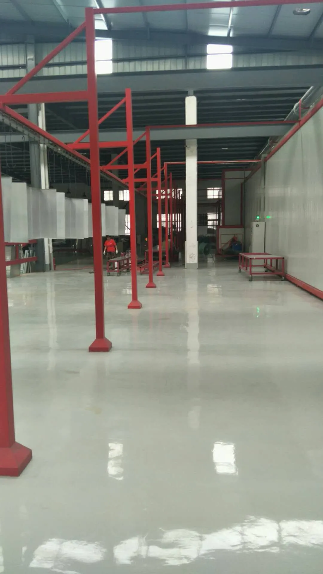
Achieving Temperature Uniformity & Performance
How Forced Air Circulation Maintains Even Heat Distribution
Temperature uniformity depends almost entirely on air circulation rate and ducting design. Here's the physics:
Without circulation, heat rises and stratifies. The top of the chamber reaches setpoint temperature first; the bottom remains cooler. Workpieces at the top cure faster and harder than those at the bottom—leading to visible color banding and hardness differences.
Forced circulation breaks this stratification. Fast-moving air from the supply duct carries thermal energy into every zone of the chamber simultaneously. Return air re-enters at low velocity (bottom of chamber), so it gradually gains heat as it travels through the chamber volume before exiting back to the circulation fan.
This creates a continuous loop: every cubic centimeter of chamber air is heated and recirculated 3–4 times per minute, so temperature gradients flatten rapidly.
Best practice: measure actual air velocity at 3–4 points within the chamber using a handheld anemometer. You should see fairly consistent velocity (within ±20%) across the chamber cross-section. If velocities vary by more than 30%, redesign your ducting or reposition supply outlets.
Preventing Temperature Stratification (Top vs. Bottom)
Common mistake: installing a single large supply duct at the top of the chamber. This creates a high-velocity jet that overheats the top while leaving the bottom cold.
Better approach:
- Use multiple smaller supply ducts (ideally 4–6 distributed around the chamber perimeter)
- Angle supply outlets at 30–45° downward to encourage air to mix as it travels through the chamber
- Include a return air chamber below the workpiece conveyor level
- Size the return opening so return air velocity is low (0.5–1.0 m/s), allowing air to "settle" and pick up even heating as it exits
Another effective strategy: install a false floor or baffle inside the chamber to create a uniform return air plenum. This ensures return air doesn't bypass sections of the chamber.
Sealing & Insulation Best Practices
Even small air leaks dramatically reduce efficiency. A 1% gap in sealing can result in 5–10% energy waste.
Checklist:
- Inspect all rivet holes before assembly. Replace any that are oversized (>1/16" larger than rivet).
- Apply sealant to all interior seams before insulation is installed.
- Use high-temperature gasket material (not generic RTV) at all access doors and thermocouple ports.
- Allow sealant to fully cure before operating the oven. Partially cured sealant can off-gas and contaminate coatings.
- Periodically (every 6–12 months) inspect exterior surface temperature. If any zone is more than 20°C hotter than neighboring zones, suspect insulation compression or sealant failure in that area.
Insulation compression over time reduces R-value. If your external surface temperature gradually increases year-over-year, add a supplementary insulation layer or plan for oven de-rating (reduce throughput to lower internal temperature and extend equipment life).
Safety Considerations & Common Installation Mistakes
Overpressurization & Ductwork Sealing
A common and dangerous error: oversizing the circulation fan so that internal pressure exceeds external atmospheric pressure significantly (>10 Pa).
Overpressurization causes:
- Forced leakage at poorly sealed seams (energy waste)
- Pressure on access doors, causing them to blow open during operation
- Powder being forced into seams and crevices, creating ignition hazards
- Operator discomfort (difficulty opening doors under pressure)
Solution: balance supply and return airflow. Measure pressure at the chamber center using a manometer. Maintain slight negative or neutral pressure (±5 Pa). If the chamber pressurizes, reduce fan speed or open return air dampers.
Ductwork sealing: all ducts between the fan and chamber, and between the chamber and return, should be sealed with high-temperature foil tape or caulk. Flexible ducts should be mechanically clamped (not just pressed together) at all connections.
Load-Bearing & Floor Support Requirements
The oven floor must support:
- Static weight of insulation, casing, and frame (typically 2–5 tons for a medium oven)
- Dynamic loads from workpieces traveling through
- Thermal stress from repeated heating and cooling
Install the oven on a reinforced concrete floor (minimum 150mm thick, minimum 20 MPa compressive strength). Soft floors (wooden platforms, cracked concrete) can lead to settling, frame warping, and eventual thermal performance degradation.
Use adjustable leveling feet or shims to ensure the oven frame is level (within ±5mm over a 2m span). Even slight tilts cause uneven conveyor loading and thermal bypass paths.
For tall ovens (>2.5m), consider cross-bracing or external support to prevent tipping if the door is opened suddenly or if lateral loads are applied.
Working with High-Temperature Insulation (PPE & Health)
Rockwool and fiberglass insulation can irritate skin and respiratory systems if fibers are inhaled during installation.
Safety measures:
- Wear a P100 or N95 respirator when cutting, fitting, or handling insulation boards
- Wear long sleeves, gloves, and eye protection
- Ensure adequate ventilation in the assembly area
- Wash hands and exposed skin thoroughly after handling insulation
- Do not install insulation in very high-wind areas (wind can disturb fibers)
Once the outer casing is in place, the insulation is fully enclosed and poses no ongoing health risk.
Structural Rigidity & Prevention of Warping
Thermal cycling (repeated heating to 200°C and cooling to ambient) stresses the frame and fasteners.
Prevention:
- Use lock washers or thread-locker compound on all bolts
- Check fastener torque monthly for the first 6 months of operation
- Periodically inspect the frame for signs of cracking or separation at welds/rivets
- Ensure the oven is mounted on a stable, vibration-free platform (avoid proximity to heavy machinery or impact zones)
- If the oven will be moved or transported, reinforce the frame with temporary bracing during transport
Frame warping typically manifests as:
- Uneven door closure (door binds at one corner)
- Visible gaps between casing panels
- Hot spots appearing at irregular locations (indicating insulation separation)
If warping develops, it usually indicates undersizing during the design phase. Remedy: add supplementary external bracing, or plan for oven de-rating (lower throughput to reduce thermal stress).
Integration with Your Coating Line & Troubleshooting
Matching Oven Capacity to Production Speed & Dwell Time
The oven must be sized not just by chamber dimensions, but by throughput capacity.
Dwell time is the duration a workpiece must spend at cure temperature to fully harden. Typical values:
- Epoxy powder: 10–15 minutes at 200°C
- Polyester powder: 8–12 minutes at 220°C
- Hybrid (epoxy-polyester) powder: 10–15 minutes at 200°C
Consult your powder supplier's technical sheet for exact cure schedules.
Throughput formula:
- If your oven is 5m long and workpieces move at 0.5 m/min, dwell time = 5m ÷ 0.5 m/min = 10 minutes ✓ (matches epoxy powder requirement)
- If workpieces move at 1.0 m/min, dwell time = 5m ÷ 1.0 m/min = 5 minutes ✗ (too fast; coating will undercure)
To increase throughput without undercuring:
- Extend the oven length (adds dwell time)
- Slow the conveyor
- Run multiple items in parallel (separate conveyor lanes)
- Increase oven temperature (reduces required dwell time, but risks overcuring)
We've observed that many operations install ovens that are too short for their actual production speed. Result: chronic undercuring complaints. Undersized ovens are expensive to remedy (requires reconstruction or replacement).
Our recommendation: size the oven for 20–30% longer dwell time than the powder supplier specifies. This margin accommodates temperature swings, load-stacking effects (multiple workpieces damping oven temperature), and future powder type changes.
Common Curing Defects & Adjustment Solutions
| Defect | Root Cause | Solution |
|---|---|---|
| Undercure (soft coating, poor hardness) | Temperature too low or dwell time too short | Increase oven setpoint by 10–20°C; slow conveyor to extend dwell time; check that thermostat sensor is positioned at true chamber center |
| Overcure (coating brittle, discolored) | Temperature too high or dwell time too long | Reduce setpoint; increase conveyor speed; verify sensor isn't positioned in a hot zone |
| Color banding (top/bottom different colors) | Temperature stratification | Increase circulation fan speed; check for blocked supply ducts; verify return air dampers are open |
| Surface bubbles or pinholes | Moisture or trapped gas in workpiece | Extend preheat time in oven; lower oven humidity; check that pre-treatment (phosphate/zinc pretreat) is complete |
| Adhesion failure (coating peels) | Poor pre-treatment or cold spot | Verify pre-treatment process (phosphate is critical); increase pre-heating time; check for cold zones with a thermal imaging camera |
| Orange peel texture | Powder flow issue or oven sag | Increase cure temperature by 10°C to improve melt flow; check that heating is uniform across chamber |
Maintenance & Long-Term Durability
Monthly checks:
- Inspect external surface temperature (use an infrared thermometer). Any zone >15°C hotter than neighbors indicates insulation degradation or air bypass.
- Check door seals for cracks or heat damage. Replace if compromised.
- Verify thermostat setpoint hasn't drifted. Cross-check with a calibrated thermometer.
- Listen for unusual fan noise or vibration. Change fan bearings every 3–5 years.
Quarterly checks:
- Inspect interior for powder buildup or dust accumulation. Remove debris with compressed air or a stiff brush (do not use aggressive vacuums, which can disturb insulation).
- Test heater elements for continuity (electrical resistance shouldn't increase by more than 10% from baseline).
- Check all fasteners and tighten any that have loosened.
Annual maintenance:
- Remove and inspect the thermostat sensor. Clean any dust or powder residue. Recalibrate if accuracy has drifted.
- Inspect ductwork for leaks or separations. Re-seal with foil tape if needed.
- Measure actual air velocity at chamber interior. Compare to design baseline. A 20% drop indicates fan wear or duct blockage.
- Document all maintenance and temperature logs for future reference.
Expected service life:
- Electric elements: 5–10 years (longer if lightly cycled)
- Gas burners: 3–7 years (more dependent on combustion quality and fuel type)
- Insulation: 10–15 years (depends on thermal cycling frequency and environmental exposure)
- Frame and structure: 15–25 years if properly maintained
If operating hours exceed 50,000 (roughly 10 years at 50 hours/week), plan for complete overhaul or replacement.
Comparison Table: Electric vs. Gas Heating
| Factor | Electric | Gas |
|---|---|---|
| Initial Cost | $1,200–$3,500 (small) | $2,500–$5,000 (small) |
| Operating Cost (per kWh equivalent) | Higher (~$0.12–$0.15/kWh) | Lower (~$0.08–$0.10/kWh) |
| Warm-up Time | 30–40 min (cold start) | 15–20 min (cold start) |
| Temperature Stability | Excellent (±5°C) | Good (±10°C, if burner tuned) |
| Maintenance | Minimal (annual inspection) | Moderate (burner service, gas line inspection) |
| Safety Complexity | Low | Higher (combustion hazards, gas line safety) |
| Best for | Job-shop, frequent color changes, small throughput | High-volume continuous production |
| Environmental Impact | Low emissions (electricity source dependent) | Direct CO₂ emissions |
Selecting the Right Oven Configuration for Your Production
When designing or purchasing a powder coating oven, prioritize these factors in order:
1. Dwell Time First
Calculate the minimum oven length needed to achieve required cure dwell time at your production speed. Undercuring is not worth any cost savings.
2. Temperature Uniformity Second
Invest in good circulation design and insulation. A $500 improvement in ductwork design eliminates far more quality problems than a $5,000 equipment upgrade later.
3. Heating Method Third
Choose heating type based on your production volume and available utilities. Gas is cheaper to operate at high volumes; electric is more reliable and flexible for smaller operations.
4. Control System Fourth
Invest in dual temperature sensors, a quality thermostat, and data logging. These typically add $500–$1,500 but prevent costly quality failures.
5. Maintenance Access Last
Ensure the oven is designed for easy inspection and cleaning. Poor accessibility leads to neglected maintenance and premature failure.
Conclusion
Building or selecting a powder coating oven requires understanding the four core systems: the insulated chamber, heating apparatus, air circulation network, and temperature control. Undersizing any of these leads to chronic quality or efficiency problems that are expensive to remedy.
From our experience working with cabinet makers, furniture producers, and aluminum extruders, the most common mistakes are:
- Ovens too short for the required dwell time
- Inadequate air circulation (poor mixing, stratification)
- Oversized or undersized heaters (leading to temperature instability)
- Poor sealing and insulation (high energy waste)
We recommend:
- Size for 20–30% longer dwell time than powder specifications require, to accommodate thermal margins and future flexibility.
- Install dual temperature sensors: one for control, one for safety. This catches problems before they affect product quality.
- Prioritize air circulation design over raw heating power. A well-mixed 150°C oven outperforms a poorly mixed 220°C oven.
- Plan for maintenance access from the design phase. Include cleanout ports, removable ceiling panels, and external component mounting.
- Document baseline performance (temperature profile, energy consumption, cure results) in your first month of operation. Use this as a reference for detecting future degradation.
Whether you're building a custom oven or evaluating commercial equipment, these principles will guide you toward a reliable system that delivers consistent coating quality for years to come.
If you're planning a complete powder coating line—including pre-treatment, spray booth, curing oven, and recovery systems—we're here to help. We've supported hundreds of manufacturing facilities across cabinet, furniture, and metal component sectors to design integrated solutions tailored to their products and production needs.
Contact us today to discuss your powder coating system requirements. We provide detailed system assessments, custom equipment design, and full installation and training support to ensure your line performs optimally from day one.
WhatsApp: +8618064668879
Email: ketumachinery@gmail.com